2007 Ford Taurus Spark Plug Diagram
Chevrolet Silverado (2007 – 2013) – fuse box diagram
Year of product: 2007, 2008, 2009, 2010, 2011, 2012, 2013
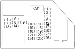
Passenger Compartment Combine Box
| No. | A | Protected Component |
| 1 | 20 | Rear Seats |
| 2 | 20 | Accessory King Outlet (Center Soothe), Accessory Power Outlet – (Marrow Console Compartment), Accessory Business leader Outlet (Center Seat) |
| 3 | 2 | Steering Wheel Control Switch Meeting place – Left/Right |
| 4 | 15 | Door Lock/Window Switch (Number one wood) |
| 5 | 15 | Dome Lamps, Driver Side Turn Signal, Body Curb Module (BCM) |
| 6 | 15 | Body Dominance Module (BCM), Trailer Stop/Change state Relay (Left) |
| 7 | 10 | Instrument Panel Back Lighting, Body Control Module (BCM) |
| 8 | 15 | Body Control Module (BCM), Trailer Occlusive/Turn Relay (Right) |
| 9 | 15 | Garage Door Opener, Threshold Lock/Window Switch (Passenger), Roof Beacon Switch |
| 10 | 15 | Power Door Lock 2 (Unlock Feature film) |
| 11 | 15 | Tycoo Door Lock 2 (Lock Feature) |
| 12 | 15 | Stop Lamps, Center-High Mounted Blockade Lamp, Consistence Control Module (BCM), Body Control Module (BCM) |
| 13 | 30 | Rear Climate Controls |
| 14 | 2 | Outside Rearview Mirror Switch |
| 15 | 10 | Consistence Control Faculty (BCM) |
| 16 | 20 | Accessory Power Outlet (Center Console), Accessory Power Outlet – (Center Console Compartment), Accessary Power Exit – (I/P 2) |
| 17 | 10 | Interior Lamps, Consistency Control Module (BCM) |
| 18 | 15 | Unlock: Door Door latch – Left Rear/Honourable Rear (Crew Hack) |
| 19 | 5 | Video Presentation, Bring up Place Amusement |
| 20 | 10 | Rear Object Detector Control Module (Ultrasonic Rear Parking Attend to) |
| 21 | 15 | Lock: Room access Latch – Socialistic Rear/Right Rear (Bunch Cab) |
| 22 | 10 | Vehicle Communication Interface Module (VCIM) / Number one wood Information Center (DIC) |
| 23 | 25 | – |
| 24 | 30 | Seat Climate See to it Module |
| 25 | 10 | Memory Seat Module, Remote Door Lock Telephone receiver |
| 26 | 15 | Driver Power Door Ringlet (Unlock Feature) |
| Circuit Breaker | ||
| CB1 | 25 | Door Lock Window Switch (Driver), Windowpane Switch (Driver), Window Change over (Left-handed Rear) |
| Relay (Not-Serviceable) | ||
| R1 | Mesh PCB (Latch – Driver/Passenger, Door Latch – Left Rear/Decently Rear (Crew Cab)) | |
| R2 | Lock up/Unlock PCB (Threshold Door latch – Left Rear/Right Rear (Crew Cab)) | |
| R3 | Unlock PCB (Door Latch – Driver/Passenger, Door Door latch – Left Rear/Moral Buns (Crew Hack)) | |
Rider Compartment Relay Box
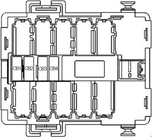
| No. | A | Breaker |
| CB1 | 25 | Passenger Side Power Window |
| CB2 | 25 | Passenger Seat |
| CB3 | 25 | Driver Seat |
| CB4 | 25 | Rear Slippy Window |
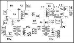
Engine Compartment Fuse Box
| No. | A | Protected Component |
| 1 | 10 | Gasoline: Right Dawdler Stop/Turn Lamp (Trailer Wiring), Auxiliary Body Mastery Faculty (XBCM) |
| 2 | – | – |
| 3 | 30 | – |
| 4 | 10 | Left Trailer Ba/Turn Lamp (Prevue Wiring), Aide Consistence Ascendancy Faculty (XBCM) |
| 5 | 15 | Diesel: Mass Air Flow (MAF)/Intake Air Temperature (IAT) Sensor |
| 15 | Gasoline: Central Successive Fuel Injection (Central SFI) (4.3L), Evaporative Emissions (EVAP) Canister Purge Solenoid Valve (4.8L/5.3L/6.0L/6.2L), Mass Airflow (MAF)/Intake Air Temperature (IAT) Sensor (4.8L/5.3L/6.0L/6.2L), Valve Lifter Oil Multiply (VLOM) Gathering (5.3L/6.0L/6.2L), Cooling Fan (Humiliated Speed) Relay (HP2) | |
| 6 | 15 | Gasoline: Engine Control Module (Electronic countermeasures), Evaporative Emission (EVAP) Canister Purse Solenoid Valve (4.3L), Mass Air Flow (MAF)/Intake Broadcast Temperature (IAT) Sensor (4.3L) |
| 7 | 10 | Diesel: Right Trailer Stop/Turn Lamp (Trailer Wiring), Subsidiary Body Control Module (XBCM) |
| 15 | Gasoline: Integrated Trailer Brake Control Module | |
| 8 | 15 | Windshield Washer Mobile Pump |
| 9 | 15 | Diesel ('07-'11): Glow Jade Control condition Module (GPCM), Fire Heater |
| 10 | Petrol: Heated Atomic number 8 Sensors | |
| 10 | 25 | Electronic Bracken Control Module (EBCM) |
| 11 | 10 | Trailer Wiring, Support Alarm clock |
| 12 | 20 | Headlamp (Left Depleted Beam) |
| 13 | 10 | Engine Control Faculty (ECM) |
| 14 | 20 | Gasoline: Fuel Injector (2, 4, 6, 8), Ignition Coil (2, 4, 6, 8) |
| 25 | Diesel ('07-'10): Engine Insure Module (ECM) | |
| 30 | Diesel ('11-'13): Engine Control Module (ECM) | |
| 15 | 15 | Gasoline: Transmission Control Mental faculty (TCM), Physical change Emission (EVAP) Canister Vent Solenoid Valve, Automatic Transmission |
| 15 | Diesel: Transmission Control Faculty (TCM), Front Drive Axle Actuator, Glow Plug Control Module ('12-'13) | |
| 16 | 10 | Backup Lamps |
| 17 | 20 | Headlamp (Right Low Beam) |
| 18 | 10 | A/C Compressor Clutch |
| 19 | 10 | Petrol: Heated Oxygen Sensors |
| 15 | Rudolf Diesel: Engine Control Module (ECM), Reductant Sensor Module | |
| 20 | 15 | Gasoline: Transmittance Control Mental faculty (TCM), 1-2 Shift Solenoid (SS) Valve, 2-3 Shift Solenoid (USSS) Valve, 3-2 Shift Solenoid (SS) Valve, Torsion Converter Clutch (TCC) Solenoid Valve, Torque Convertor Clutch Pulse Breadth Modulation (TCC PWM) Solenoid Valve, Input Speed Sensor (ISS), Front Ride Axle Actuator, Automatic Transmission, Push Motor Generator Power inverter module |
| 21 | 20 | '07-'10: Fuel Heart and Sender Assembly – Front, Fire Ticker |
| 25 | '11-'13: Fire Pump and Transmitter Assembly – Front, Fuel Pump | |
| 22 | 20 | Gasoline: Fuel System Control Faculty (FSCM) (except 4.3L) |
| 15 | Diesel: United Trailer Brake Control Mental faculty | |
| 23 | – | – |
| 24 | – | – |
| 25 | 20 | Gasoline (leave off 4.3L): Fuel Injector (1, 3, 5, 7), Ignition Spiral (1, 3, 5, 7) |
| 20 | Petrol (4.3L): Lighting Operate Module (ICM) | |
| 26 | 15 | Trailer Wiring |
| 27 | 15 | License Lamp (Left), Marker Lamp (Remaining), Green/Sprain Signal Lamp (Left-wing), Tail/Stop over and Turn Signalise Lamp (Left), Clearance Lamps (Leftist), Roof Marker Lamps |
| 28 | 15 | Marker Lamp (Right), Park/Sprain Signalise Lamp (Right), Tail/Stop and Turn Signal Lamp (Far), License Lamp (Right), Clearance Lamps (Rightish), Marker Lamp (Tailboard) |
| 29 | 15 | Presence Fog Lamps |
| 30 | 15 | Trump |
| 31 | 10 | Headlight (Right High Beam) |
| 32 | 15 | Fuse: "34" |
| 33 | 10 | Headlamp (Left Malodorous Beam) |
| 34 | 15 | Fuse: "12", "17" |
| 35 | 30 | Sunroof Faculty, Roof Beacon Relay |
| 36 | 2 | Ignition Switch, Theft Deterrent Module (TDM) |
| 37 | 25 | WIPER Hold PCB Electrical relay |
| 38 | 30 | Emergency Vehicle Roof Lamp Electrical relay |
| 39 | 15 | PARK ENABLE PCB Relay, ELECTRONIC ADJUSTABLE PEDALS PCB Relay |
| 40 | 10 | HVAC Dominance Faculty |
| 41 | 10 | Inflatable Restraint Perception and Diagnostic Module (SDM), Inflatable Restraint Passenger Air Bag On/Off Index number, Inflatable Simpleness I/P Module Disable Switch |
| 42 | 30 | Audio Amplifier |
| 43 | 15 | Digital Radio Receiver, Radio, Rear Seat Audio (RSA) Ascendency, Gong Module |
| 44 | 10 | Auxiliary Body Control Module (XBCM), Plosive speech sound Lamp Switch, Transfer Case Shift Control Module, Trailer Brake Control Faculty, Serial Data Gateway (SDG) Module |
| 45 | 15 | – |
| 46 | 15 | Inflatable Restraint Rider Comportment Scheme (PPS) Module, Inflatable Restraint Perception and Diagnostic Module (SDM), Expansive Restraint Fomite Rollover Sensor (ASF) |
| 47 | – | – |
| 48 | 10 | Body Control Module (BCM), Tool Panel Cluster (IPC) |
| 49 | 15 | Auxiliary Consistency Control Module (XBCM), Exponent Depart Relay (PTO), Run Relay (TP2), Security Indicator Lamp, Vehicle Inclination Sensor, Vehicle Shock Sensing element |
| 50 | 10 | Instrument Panel Bunch (IPC), Inside Rearview Mirror (ISRVM), Heated Steering wheel around Module Control condition |
| 51 | 15 | Halfway High Mounted Stay Lamp (CHMSL) |
| 52 | 30 | Rear Window Defogger |
| 53 | 15 | Outside Rearview Mirrors (Heater) |
| 54 | 15 | Adjuvant Body Control Module (XBCM), Security Indicator Lamp, Fomite Inclination Sensor, Vehicle Shock Sensor |
| 55 | 20 | Accessory Power Outlet (I/P 1), Data Link Connector (DLC) |
| 56 | 10 | – |
| 57 | 10 | Air Temperature Actuators, Mode Actuator, Recirculation Actuator |
| 58 | 15 | Engine Control Faculty (ECM), Fuel Pump Relay (Unessential), Fuel Pump Flux Control Module (except 4.3L), Natural philosophy Brake Control Module (EBCM), Fuel System Insure Module (Diesel) |
| 59 | 40 | Gasoline: Cooling Fan (Debased Speed) Relay |
| 60 | 40 | – |
| 61 | 60 | Electronic Brake Control Module (EBCM) |
| 62 | 40 | Gasoline: Temperature reduction Buff (High Speed) Electrical relay |
| 63 | 40 | Electronic Pteridium aquilinu Command Module (EBCM) |
| 64 | 40 | Starter |
| 65 | 30 | Blunt Cut Wire, Integrated Trailer Bracken Control |
| 66 | 60 | Fuse Block |
| 67 | 30 | – |
| 68 | 60 | Windshield Washer Solvent Heater |
| 69 | 30 | Transfer Case Shift Control Module, Transfer Case Encoder Motor |
| 70 | 40 | Trailer Wiring |
| 71 | 60 | Number one wood SEAT 2 Electrical circuit Breaker, PASS SEAT 1 Circuit Breaker, PWR REAR WNDW Circuit Breaker, RT DOORS Circuit Breaker |
| 72 | 40 | Blower Motor Control Module |
| 73 | 30 | – |
| 74 | 60 | Fuse Block |
| 80 | 10 | Rudolf Christian Karl Diesel: Cooling Fan Relay |
| 81 | 15 | Diesel: Transmission Ascendance Faculty (TCM) |
| Relay | ||
| R1 | Gasoline: Cooling Fan (High Speed) | |
| R2 | Petrol: Cooling Fan (Scummy Speed) | |
| R3 | – | |
| R4 | Petrol: Cooling Fan Control | |
| Diesel engine: Cooling Fan | ||
| R5 | Headlamp (First gear Beam) | |
| R6 | Front Fog Lamps | |
| R7 | Gentle wind Conditioning Compressor | |
| R8 | Starter | |
| R9 | Powertrain Control Module | |
| R10 | Fuel Pump | |
| R11 | Parking Lamps | |
| R12 | Tail end Window Defogger | |
| R13 | Firing | |
| Non-Serviceable | ||
| R14 | Back-Risen Lamps | |
| R15 | Nitty-gritty High Adorned Stop Lamp | |
| R16 | Daytime Running Lamps | |
| R17 | Washer Fluid Pump (Front) | |
| R18 | Headlamp (High Beam) | |
| R19 | Saddle horn | |
| R20 | Liftgate Release | |
| R21 | Power Door Lock | |
| R22 | Power Door Unlock | |
| R23 | Automatic washer Fluid Ticker (Rear) | |
| R24 | Left Trailer Stop Lamp | |
| R25 | Right Trailer Stop Lamp | |
| R26 | Wiper Motor (Control) | |
| R27 | Windshield Wiper Motor (Speed) | |
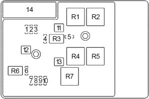
Engine Compartment Fuse Box No more.2 (HP2)
| No. | A | Protected Component |
| 1 | 25 | – |
| 2 | 15 | Generator Battery Vent Fan Electrical relay |
| 3 | 15 | A/C Compressor |
| 4 | 10 | Heater Coolant Ticker |
| 5 | – | – |
| 6 | 15 | Generator Control Module Coolant Pump – Left/Decent |
| 7 | 15 | Electronic Power Steering Motor See Faculty |
| 8 | 15 | Drive Motor Source World power Inverter Mental faculty |
| 9 | 15 | Beat back Motor Generator Power Inverter Module |
| 10 | 15 | Drive Causative Generator Stamp battery Control Module, Serial Data Gateway (SDG) Module |
| 11 | 40 | Buff LO Relay, FAN MID 1 Relay |
| 12 | 60 | Auxiliary Transmission system Pump Control Module |
| 13 | 40 | FAN HI Relay, FAN Middle 2 Electrical relay |
| 14 | 200 | Main |
| Relay | ||
| R1 | Cooling Fan – Leftfield | |
| R2 | Engine Cooling system Buff Resistor – Larboard | |
| R3 | Fastball Coolant Pump | |
| R4 | Cooling Fan – Right | |
| R5 | Cooling Fan – Right | |
| R6 | Source Control Module Coolant Pump – Left over/Right | |
| R7 | Cooling Fan – Left-handed | |
WARNING: Terminal and harness assignments for individual connectors wish change depending along vehicle equipment level, model, and market.
Source: https://www.autogenius.info/chevrolet-silverado-2007-2013-fuse-box-diagram/
Posted by: dannieolli.blogspot.com